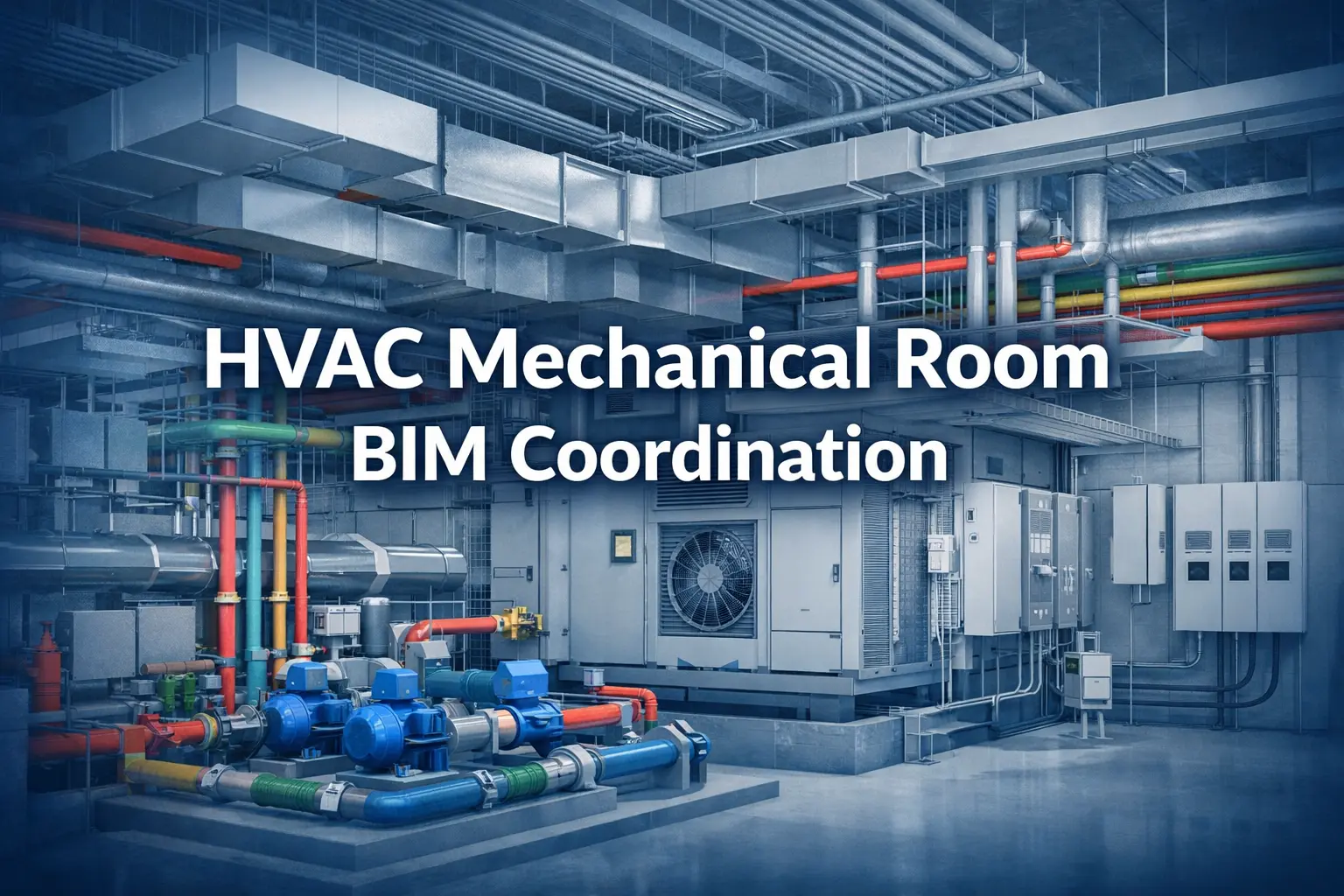
HVAC mechanical room BIM coordination is the process of modeling all MEP, structural, and architectural systems in a federated 3D environment — then detecting and resolving every conflict before fabrication or construction begins. It is the single most effective way US contractors eliminate field rework, failed inspections, and maintenance access problems on commercial projects.
Why Mechanical Rooms Are the Hardest Zone on Any Commercial Project
A mechanical contractor on a 14-story commercial project sets a 30-ton air handling unit in the basement mechanical room. Steel is topped out, drywall is going up. Then someone checks the coil-pull clearance: the unit is 14 inches from the chilled water header. The manufacturer needs 48 inches minimum. Moving the AHU means relocating a 12-inch main that’s already been fabricated and partially installed. Final cost: $67,000 in rework and three weeks of schedule loss.
That story is not unusual. It plays out on US commercial projects every week — different cities, different equipment, same root cause: mechanical room coordination done on 2D drawings that cannot capture the spatial reality of what’s actually being built.
Mechanical rooms are where every building trade converges — AHUs, chillers, boilers, chilled water and heating water headers, electrical panels, MCCs, VFDs, fire protection risers, and plumbing connections — all competing for a footprint that is almost always undersized. Each discipline engineer designs independently, on separate drawing sets, at different project stages. The conflicts that look manageable on paper become physical objects in the same room.
Mechanical rooms generate more coordination clashes per square foot than any other zone on a commercial project — and they’re the last place you want to find a problem.
HVAC mechanical room BIM coordination solves this by building a federated 3D model of every system before construction begins. Every conflict is found, triaged, assigned, and resolved while it’s still just geometry on a screen — not fabricated steel on a jobsite.
⚠ Industry research puts the annual cost of US construction rework caused by unresolved clashes at $31.3 billion (FMI/Autodesk). Mechanical rooms are the single largest source of those conflicts on commercial projects.
The 3 Types of Clashes You Must Resolve
1. Hard Clashes — Two Objects in the Same Physical Space
A hard clash is unambiguous: a duct penetrates a structural beam, a pipe intersects an AHU casing, a conduit runs through a pump body. These must be resolved before any fabrication begins. In a mechanical room, they most commonly occur at the supply duct trunk at the room wall (directly below major beams), overhead pipe rack zones, and equipment pad areas where piping, structural supports, and slab penetrations converge in a tight zone.
2. Soft Clashes — Insufficient Clearance for Operation, Access, or Code Compliance
Soft clashes are the most dangerous type because they pass a basic visual check. Two elements don’t physically touch — but the gap between them violates a manufacturer specification, maintenance access requirement, or code clearance. They are only caught when clearance zones are explicitly modeled as 3D geometry and tolerances are set to spec, not to the Navisworks default.
| Soft clash type | Requirement | What gets missed on 2D |
|---|---|---|
| AHU coil-pull clearance | 48"+ clear on coil-pull face (manufacturer spec) | Not shown on design drawings — discovered at first service call |
| Chiller tube-pull zone | 8–15 ft clear at one end of unit | Routinely violated by adjacent pipe runs or structural columns |
| NEC panel working clearance | Min. 36" in front of all panels, MCCs, and VFDs (NEC 110.26) | Pipe headers frequently encroach — caught at electrical inspection |
| Pump impeller access | Vertical overhead clearance for maintenance removal | Blocked by low pipe headers or cable trays — deferred maintenance |
| Boiler service access | All-sides clearance for combustion testing and heat exchanger service | Equipment set too close to walls or adjacent boilers — fails commissioning |
3. Workflow (4D) Clashes — Sequencing Conflicts Between Trades
A 4D clash is a scheduling conflict, not a geometric one. Two trades need the same zone at the same time or in the wrong sequence: equipment pads poured after the delivery window, spools fabricated before submittal approval changes flange ratings, overhead rough-in scheduled after equipment is set and blocks all access. Navisworks 4D simulation links the coordinated model to the project schedule and catches these conflicts in preconstruction before anyone commits to fabrication or delivery.
The HVAC Mechanical Room BIM Coordination Process — Step by Step
Here is how a professional HVAC mechanical room BIM coordination effort unfolds from input drawings to clash-free fabrication-ready deliverables.
| Step | What happens and why it matters |
|---|---|
| 1. Collect all discipline inputs | Gather current-revision drawings from every trade sharing the mechanical room: architectural, structural, mechanical (including equipment submittals with certified dimensions), electrical, plumbing, and fire protection — all at the same revision. The most common setup error: mismatched coordinate origins between discipline files. Confirming alignment before modeling begins eliminates hundreds of false clashes. |
| 2. Build the HVAC model in Revit | Model at LOD 300 for design coordination or LOD 400 for fabrication. The key distinction: LOD 400 requires equipment families built to manufacturer-certified dimensions including 3D access zone geometry — coil-pull clearances, tube-pull zones, and service access volumes modeled as solid geometry that will trigger soft clashes. Ductwork sized and detailed to SMACNA standards; pipe sized and routed per the mechanical engineer’s specifications. |
| 3. Federate the model in Navisworks | Link all discipline NWC files into a single Navisworks session. Confirm coordinate alignment across all files. Configure clash test rules — which discipline pairs to test, what tolerance to use, whether clearance zone geometry is active. This configuration step is the most commonly skipped and the most consequential: wrong tolerances produce thousands of false positives that obscure real conflicts. |
| 4. Run clash tests and triage results | The first clash test on a complex mechanical room typically returns 300 to 1,000+ flagged items. This is expected. Triage into Critical (hard clashes or code violations — resolve before any fabrication), Major (soft clashes affecting access or maintenance — resolve before construction documents are issued), and Minor (acceptable tolerance overlaps — document and formally accept). Assign every Critical and Major clash to the responsible trade with a resolution deadline. |
| 5. Weekly coordination meetings and model updates | Each trade updates their Revit model within 48–72 hours of an agreed resolution. The federated model is refreshed, clash tests re-run, and results reviewed in the next weekly coordination meeting. For a complex mechanical room, expect 3–5 coordination rounds before the model reaches clash-free status at the Critical and Major levels. Formal sign-off by all parties on the coordination log is essential — it protects every trade if field conditions deviate. |
| 6. Extract coordinated deliverables | Coordination drawings (2D plans and sections from the 3D model), LOD 400 shop drawings for pipe spools and duct sections, structural sleeve and penetration drawings issued to the structural engineer for approval, and the signed clash resolution log. Every dimension on every shop drawing traces back to the coordinated 3D model — not to a 2D design drawing that may have already been superseded. |
✔ Start mechanical room BIM coordination at 50% design documents — before structural steel is fabricated, equipment pads are poured, or pipe spools are ordered. Every week earlier you start, the cheaper every clash resolution becomes.
5 Mechanical Room Coordination Challenges — and How BIM Solves Them
1. AHU Placement and Coil-Pull Clearance
The mechanical design drawing shows the AHU in a position that looks fine on a 2D plan. In 3D, the coil-pull clearance zone — often 48 to 72 inches depending on unit size — is completely blocked by adjacent pipe headers or walls. This is the most expensive single clash type in a mechanical room.
BIM solution: Model the AHU with the manufacturer’s certified access zone geometry as solid 3D volumes. Any element entering the clearance envelope triggers a soft clash before a single equipment pad is poured. Coordinate with structural for pad dimensions and anchor bolt locations at the same time.
2. Chilled Water Header Congestion at the Ceiling
Chilled water supply and return, condenser water supply and return, and heating hot water supply and return mains — each 8 to 14 inches in diameter, up to 18 inches with insulation — run parallel at the ceiling before branching to serve the building. Add structural beams, electrical cable trays, and fire protection branches, and a ceiling that may only be 3 to 4 feet deep, and you have the most congested coordination zone on the project.
BIM solution: Model all pipe headers at actual outside diameter plus insulation thickness. Coordinate vertical stacking order — HVAC piping takes ceiling priority, electrical below, fire protection integrated around available space — in 3D before any fabrication. No guessing, no field arguments.
3. Supply Duct Conflicts with Structural Beams at the Room Entry
The main supply duct trunk leaving the mechanical room almost always hits a major structural beam or transfer girder at the room wall. On a 2D drawing it looks clear. In 3D, the duct depth plus beam depth plus required clearances make the 2D solution impossible without a duct offset, a beam penetration, or a relocation.
BIM solution: Link actual structural beam profiles from the structural model — not assumed depths from drawing notes. Route the duct around real geometry. If a beam penetration is required, coordinate size, location, and reinforcement with the structural engineer before steel is fabricated.
4. NEC Electrical Clearances Violated by Pipe Runs
NEC Section 110.26 requires a minimum 36 inches of unobstructed working space in front of all electrical panels, switchgear, MCCs, and VFDs. In dense mechanical rooms, mechanical contractors routinely route pipe headers directly into this zone — because the electrical panel locations and their clearance requirements are on a separate drawing set they may never reference.
BIM solution: Attach NEC clearance volumes as 3D geometry to every panel and MCC family. Set soft clash tolerance to zero for these volumes — any intrusion is a critical clash. Resolve every encroachment before any pipe headers are fabricated or electrical equipment is set.
5. Roof Penetrations Conflicting with Structural Framing
Rooftop cooling towers, RTUs, and exhaust fans connect to risers that penetrate the roof structure. On 2D drawings, penetration locations are typically shown schematically and confirmed in the field — where they routinely conflict with structural framing that’s already in place.
BIM solution: Model roof curbs and penetrations in the federated model. Check penetration locations against the structural roof framing model. Issue coordinated penetration drawings to the structural engineer for approval before the roof deck is installed. Zero field surprises.
Tools Used in HVAC Mechanical Room BIM Coordination
| Tool | Role in mechanical room coordination |
|---|---|
| Autodesk Revit MEP | Primary 3D modeling — HVAC systems, equipment families with manufacturer-certified access zones, pipe and duct routing at LOD 300–400 to SMACNA and ASHRAE standards |
| Autodesk Navisworks Manage | Model federation, automated clash detection with configurable discipline-pair rules and clearance tolerances, clash report generation, 4D schedule simulation |
| Trimble SysQue / Evolve Mechanical | Fabrication-level LOD 400 modeling — exact spool dimensions, specific fittings and connection types, direct export to fabrication software |
| BIMcollab / Revizto | Cloud clash issue tracking, coordination meeting management, trade-level collaboration, resolution log documentation with timestamps and sign-off |
| Autodesk BIM 360 / ACC | Cloud model sharing, version control, RFI tracking and management across the GC and all subcontractors |
| AutoCAD MEP | 2D coordination drawing extraction from the 3D model; conversion of legacy 2D design drawings for use as model input geometry |
Frequently Asked Questions
What does HVAC mechanical room BIM coordination cost?
For a standard mid-rise commercial mechanical room, full LOD 400 coordination — including clash detection, coordination meeting support, and drawing extraction — typically runs $4,000 to $14,000. Data center, hospital, and high-rise mechanical rooms with greater system density are priced higher. Every project is scoped individually.
How long does mechanical room BIM coordination take?
First clash report: 5–7 business days from receipt of complete input drawings across all disciplines. Full coordination including 3–5 resolution rounds: 3–5 weeks for a standard commercial mechanical room. Starting at 50% design documents gives the team the most schedule flexibility and keeps options open for design-stage resolutions.
What is the difference between LOD 300 and LOD 400 for mechanical rooms?
LOD 300 is appropriate for early design coordination and owner review — it establishes approximate equipment locations, duct routing, and pipe header sizing. LOD 400 is required for fabrication: it includes exact spool dimensions, specific fitting and flange types, insulation thicknesses, hanger locations, and manufacturer-certified maintenance clearance volumes. Shop drawings for fabrication must be derived from a LOD 400 model, not a LOD 300 model.
Do small mechanical rooms need BIM coordination?
System density determines the need, not room size. A compact mechanical room serving a high-rise with one AHU, a chilled water header array, an MCC panel, and a fire riser can generate 60 to 100 coordination clashes. Multi-trade congestion is the indicator — not square footage.
Can BIM coordination start after construction has begun?
Yes, though the value narrows as work progresses. Once structural steel is in place and equipment pads are poured, many resolutions shift from inexpensive design changes to costly field modifications. Mid-construction coordination still prevents remaining conflicts from compounding — but earlier is always significantly cheaper.
What LOD do shop drawings need to come from?
Fabrication-ready shop drawings — pipe spools, duct sections, structural support details — must come from a LOD 400 coordinated model. Every dimension on a shop drawing should be traceable back to the coordinated 3D model, not to an uncoordinated 2D design drawing.
How BuiltInBIM Experts Help You Achieve Clash-Free Mechanical Rooms
BuiltInBIM is a specialist MEP BIM coordination firm working exclusively with US commercial contractors. Our mechanical room coordination team handles the complete coordination cycle — from your first set of input drawings through to a signed, clash-free model that goes straight to fabrication and installation without surprises.
We understand that mechanical contractors are managing active jobsites, tight schedules, and lean teams. You don’t have time to chase coordination between disciplines. Our team owns that process entirely — so your team stays focused on building.
| What BuiltInBIM delivers | What it means for your project |
|---|---|
| LOD 300–400 HVAC Revit modeling | Your mechanical room fully modeled at fabrication-ready detail — ductwork, piping, equipment, and manufacturer-certified access zones — built to SMACNA standards and actual submittal dimensions, not design assumptions. |
| Navisworks clash detection with full triage | Not a raw 700-item clash dump. We sort every conflict into Critical, Major, and Minor — assign ownership to the responsible trade — and track every resolution to sign-off. |
| Soft clash detection using clearance zone geometry | AHU coil-pull, chiller tube-pull, NEC panel clearances, pump impeller access, and boiler service zones are all modeled as 3D volumes. Soft clashes are caught before a single pad is poured or spool is ordered. |
| Weekly coordination meeting support | Our coordinators attend or lead your weekly BIM coordination meetings, present clash status in 3D, and drive resolution accountability across all trades — so no clash sits unresolved for weeks. |
| Fabrication-ready shop drawings | Pipe spool drawings and duct section drawings derived directly from the coordinated LOD 400 model. Every dimension is model-based — traceable, accurate, and ready for your fabrication shop. |
| Structural sleeve and penetration drawings | Exact penetration coordinates, sizes, and sleeve specifications issued to your structural engineer for approval before any core drilling or deck forming begins. |
| Signed clash resolution log | Complete documentation of every clash identified, resolved, and accepted — required for AHJ submittals, owner handover, and trade protection if field conditions change after coordination. |
We have coordinated mechanical rooms on US commercial projects across mid-rise office, mixed-use, healthcare, data center, and high-rise residential sectors. Our team works in your time zone, attends your coordination meetings, and delivers a first clash report within 5–7 business days of receiving complete input drawings — with a written scope and turnaround commitment before we start.
✔ Whether you need full LOD 400 mechanical room coordination, a mid-project clash resolution effort, or fabrication-ready shop drawings extracted from an existing model — BuiltInBIM can scope and mobilise within days.
Ready for a Clash-Free Mechanical Room?
Tell us your project scope and we'll send you a fixed-fee coordination quote within 24 hours — LOD level, full deliverable list, and a clear turnaround timeline.

![Construction Document Sets in Revit : A Complete Guide for US Architects [2026]](https://builtinbim.com/assets/img/blog/thumbnail_Construction Document Sets in Revit.webp)