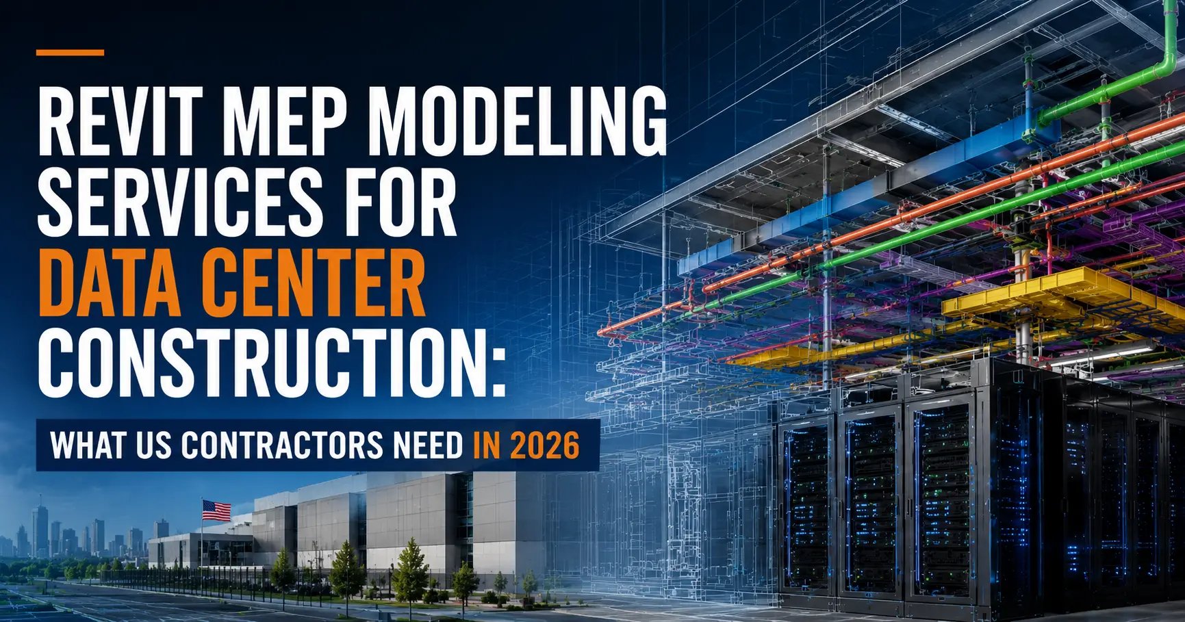
Key Takeaway: Data center starts in the USA have surged to nearly 4× average levels in 2026. These facilities are 60–70% MEP by cost — and every duct run, cable tray, and chilled water loop must be modeled at LOD 400 before a single bolt is tightened. This guide explains exactly what Revit MEP modeling delivers on data center projects, what US contractors get wrong, and how to hire the right BIM partner before schedule slippage becomes your problem.
1. Why Data Centers Are the #1 Construction Opportunity in the USA Right Now
If you are a US contractor and you have not yet positioned your business for data center work, 2026 is the year to start. Private office starts — the category that includes hyperscale and colocation data centers — have surged to nearly four times the average level seen in prior years, driven by AI infrastructure investment, cloud expansion, and digital transformation spend across every major US industry.
The numbers are not speculative. OpenAI’s Stargate project came online with 980,000 square feet and 200 MW of capacity, with plans to scale beyond 4 million square feet and 1.2 GW by mid-2026. Meta broke ground on a 900 MW facility in Wisconsin. Vantage committed $25 billion to a single Texas campus. This is not a regional trend — it is a national buildout, and it is happening faster than most contractors have adapted their workflows.
The challenge for US contractors is that data center construction is categorically different from any other commercial or industrial work. The MEP systems are denser, the code requirements are more demanding, the tolerances are tighter, and the cost of a field conflict is exponentially higher because downtime in a mission-critical facility is not acceptable.
That is exactly why Revit MEP modeling services have become the single most important procurement decision a contractor makes before a data center project breaks ground.
2. What Makes Data Center MEP Different From Standard Commercial Work
Most contractors who have delivered offices, hospitals, or warehouses underestimate data center complexity until they are on-site managing conflicts. Here is what is structurally different:
Density. Overhead cable tray density in a data center is typically three to four times higher than a standard commercial ceiling. Add cooling ductwork, chilled water piping, electrical conduit, PDUs, and fire suppression lines — and you have a ceiling plenum with essentially zero tolerance for routing errors.
Redundancy routing. Power paths in a Tier III or Tier IV facility must be physically separated. Dual routing logic for A-feed and B-feed systems creates coordination conflicts that standard clash detection rules do not automatically flag. A Revit model built without explicit redundancy routing logic will miss these conflicts every time.
Mission-critical cooling. The mechanical system — CRAC units, precision air handling, chilled water loops, cooling towers — must be coordinated with hot aisle / cold aisle containment geometry. ASHRAE A1–A4 thermal envelope requirements impose clearance and airflow logic that generic HVAC coordination does not address.
Speed. Data center projects run on compressed schedules. A build that once took 36 weeks on-site can now be completed in 16 weeks using BIM-driven prefabrication — but only if the LOD 400 model is ready before fabrication begins. Late models do not just slow things down; they eliminate prefabrication as an option entirely.
Tier standards. Uptime Institute Tier I through Tier IV classifications impose specific MEP redundancy, power, and cooling requirements. A Revit model for a Tier III facility needs to encode those requirements in the coordination logic, not treat them as a design afterthought.
3. What Revit MEP Modeling Actually Does on a Data Center Project
Revit MEP modeling is not 3D visualization. It is a data-driven workflow that produces construction-ready deliverables at every stage of a data center project.
Preconstruction coordination. A federated Revit model brings together the mechanical, electrical, plumbing, fire protection, architectural, and structural models into a single coordinated environment. Navisworks clash detection runs systematically against all disciplines, producing prioritized conflict reports — not just a list of red spheres.
Electrical room modeling. Switchgear, transformers, distribution panels, UPS systems, and generators are modeled with manufacturer-specific dimensions, arc flash boundaries, NEC clearance zones, cable entry points, conduit routing, and ventilation requirements. This is the deliverable that prevents your electricians from arriving on-site to find the switchgear does not fit the room.
Cooling system modeling. CRAC and CRAH units, precision cooling racks, chilled water piping, cooling towers, and condensate drainage are modeled with maintenance access zones, service clearance corridors, and ASHRAE-compliant airflow paths baked into the model — not marked up on a PDF afterward.
Cable tray and conduit routing. Every cable tray run is routed in installation sequence, flagged for support hanger spacing, and validated for structural load. Conduit runs are modeled with bend radii, pull points, and fill calculations.
Server room and hot/cold aisle layout. Rack layouts are modeled to maximize floor space efficiency while maintaining proper hot aisle / cold aisle containment geometry, blanking panel placement, and under-floor airflow paths.
LOD 400 fabrication deliverables. At LOD 400, every element carries manufacturer-specific dimensions, material specs, hanger locations, connection points, and installation sequencing data. These models feed directly into prefabrication — no intermediate translation step required.
4D scheduling integration. MEP systems can be tied to construction sequences in Navisworks or Synchro, allowing GCs to visualize trade conflicts in time, not just space, and sequence installation to avoid access conflicts in tight equipment rooms.
4. LOD Levels Explained: What US Contractors Need for Each Phase
One of the most common misunderstandings on US data center projects is treating LOD 300 as “good enough” when the project requires LOD 400 fabrication deliverables. Here is what each level actually means in a data center context:
| LOD | What It Contains | When You Need It |
|---|---|---|
| LOD 300 | System geometry, approximate dimensions, routing intent | Design development, permit drawings, early owner reviews |
| LOD 350 | Trade coordination, clash-resolved geometry, interface conditions | Coordination complete, construction documents issued |
| LOD 400 | Manufacturer-specific dimensions, hanger plans, cut sheets, connection details | Prefabrication, shop drawing submission, fabrication release |
| LOD 500 | As-built conditions, embedded asset data, COBie output | Facility handover, CMMS integration, digital twin development |
For most US data center projects today, the construction team needs to move from LOD 350 to LOD 400 faster than they plan for. Prefabrication windows are compressed. If your MEP subcontractors are waiting on a LOD 400 model to begin fabricating electrical skids or MEP rack assemblies, every day of model delay translates directly to schedule slippage.
5. The 6 Most Common MEP Coordination Failures on US Data Center Builds
These are the coordination failures that generate the most expensive RFIs, schedule impacts, and field rework on US data center projects. They are all preventable with a properly developed Revit MEP model.
1. Cable tray clashing with structural steel. The ceiling plenum above data halls contains structural steel at closer spacings than a standard commercial building. Cable trays routed without structural model integration routinely collide with beams, columns, and bracing — producing field rework that can run weeks.
2. Dual power feed routing without physical separation. A and B power feeds must be physically separated per Tier III and Tier IV requirements. Without redundancy routing logic built into the Revit model, clash detection will not flag a conflict between A-feed and B-feed conduit running in the same tray — because they are the same system type.
3. Electrical room clearance violations. NEC Article 110 requires specific working clearance in front of electrical equipment. Switchgear, panelboards, and transformers modeled without NEC clearance zones regularly fail inspection or require costly equipment relocation.
4. Cooling system conflicts with structural penetrations. Chilled water supply and return piping must penetrate structural walls and floors at specific locations. Without coordinated sleeve placement in the Revit model, pipe penetrations conflict with rebar and post-tensioning — requiring core drilling that delays mechanical installation.
5. Hot/cold aisle containment geometry not modeled. Blanking panels, containment doors, overhead or perimeter containment structures, and underfloor supply tile locations are frequently omitted from MEP models. The result is a cooling system that cannot achieve designed airflow efficiency, which drives up energy cost and risks equipment overheating.
6. Fire suppression head placement in dense overhead environments. NFPA 75 and NFPA 76 govern fire suppression in IT spaces. Sprinkler head obstruction by cable trays, ductwork, and overhead MEP is a common coordination miss — one that requires AHJ re-approval and delays occupancy.
6. US Code Compliance Built Into the Model: NEC, ASHRAE, NFPA
Every Revit MEP model for a US data center must be developed with the following code frameworks embedded in the coordination logic — not checked against the model after the fact:
NEC (National Electrical Code) — Article 110 working clearance requirements for electrical equipment; Article 230 service entrance requirements; Article 700 and 702 covering emergency and legally required standby systems; conduit fill calculations per Chapter 9.
ASHRAE 90.4 — Energy standard for data centers, including Power Usage Effectiveness (PUE) modeling, cooling system efficiency requirements, and the 2019 revision relaxing maximum recommended temperatures to 80°F for certain airflow configurations.
ASHRAE Thermal Guidelines for Data Processing Environments — A1 through A4 classifications defining allowable temperature and humidity ranges for IT equipment. These classifications drive the precision cooling system design and must be coordinated with server rack heat load data.
NFPA 75 and NFPA 76 — Fire protection for IT equipment and electronic computer/data processing equipment. Head spacing, suppression agent selection, and detection system placement must be modeled to comply.
NFPA 110 — Standard for Emergency and Standby Power Systems. Generator and UPS system modeling must reflect transfer switch location, fuel system routing, and exhaust routing per NFPA 110 requirements.
IBC (International Building Code) — Occupancy classification, means of egress, and structural penetration requirements as adopted by the applicable state and local jurisdiction.
Uptime Institute Tier Standards — While not a legal code, Tier certification requirements effectively function as the design standard for mission-critical facilities and must be reflected in the redundancy routing and mechanical system design within the Revit model.
A BIM partner who cannot demonstrate familiarity with all of these frameworks is not ready for data center work in the USA.
7. How BIM-Driven Prefabrication Is Cutting Data Center Timelines in Half
Prefabrication is no longer a value-engineering option on US data center projects — it is the delivery model. A data center build that once required 36 weeks of on-site MEP installation can now be completed in 16 weeks when LOD 400 BIM drives factory fabrication of MEP modules.
Here is what BIM-driven prefabrication looks like in practice:
Electrical skids. Switchgear, transformers, and distribution equipment are assembled on structural steel frames in a controlled factory environment. The skid dimensions, connection points, and anchor bolt patterns come directly from the LOD 400 Revit model — no field measurement required.
MEP rack assemblies. Mechanical, electrical, and plumbing systems are prefabricated as integrated rack modules — overhead or floor-mounted — that arrive on-site as plug-and-play assemblies. Hanger locations, pipe spool connections, and conduit termination points are embedded in the Revit model and transferred directly to the fabrication team.
Piping spools. Chilled water supply and return piping is fabricated as shop-cut and welded spool sections with exact dimensions, weld preparation, and flange specifications extracted from the LOD 400 model.
Conduit bundles. High-density conduit runs are pre-bent, labeled, and bundled for installation sequence, with pull-point locations and junction box placements verified in the model before any conduit is cut.
The critical dependency in all of these workflows is model quality. A LOD 400 Revit model with incorrect manufacturer dimensions, missing clearance data, or unresolved clashes feeds bad information directly into the fabrication process — and errors found in a factory are far cheaper than errors found on-site, but errors not found until installation are the most expensive of all.
8. People Also Ask: Honest Answers to the Questions US Contractors Are Searching
Q: How much does Revit MEP modeling cost for a data center project?
BIM coordination services for a data center typically cost between 1% and 3% of total construction cost depending on facility size, LOD requirements, and coordination complexity. For a 50,000 sq ft colocation facility, expect a range of $50,000–$150,000 for full LOD 400 MEP modeling and coordination. The ROI is significant: studies consistently show that coordinated BIM reduces RFIs by 40–60% and field rework costs by 20–30%.
Q: What LOD do I need for data center MEP shop drawings?
LOD 400 is the minimum for shop drawing submission and fabrication release. LOD 350 is sufficient for coordination completion and construction document issue. Owners requiring digital twin handover will typically specify LOD 500 with COBie data output.
Q: What is the difference between Tier II, Tier III, and Tier IV in BIM modeling terms?
Tier classification affects MEP redundancy routing requirements in the Revit model. Tier III (concurrently maintainable) requires N+1 power and cooling redundancy with physically separate routing paths. Tier IV (fault tolerant) requires 2N redundancy with fully independent, isolated systems. A Tier III model requires dual power feed routing with physical separation logic; a Tier IV model requires complete system isolation with no single point of failure — which must be modeled and clash-detected explicitly.
Q: Can I use my architect’s Revit model as the starting point for MEP coordination?
Sometimes, but with caution. Architectural models are often built for design intent and visualization, not coordination. Common issues include incorrect levels and grids, missing structural elements, non-compliant family content, and file size problems. A qualified MEP BIM team should always perform a model validation audit before beginning coordination work.
Q: How long does Revit MEP modeling take for a data center project?
For a standard colocation facility of 30,000–80,000 sq ft, expect 6–12 weeks from model intake to LOD 350 coordination complete, plus an additional 4–6 weeks to reach LOD 400 fabrication deliverables. Hyperscale campuses running 200,000+ sq ft may require parallel trade teams and 20–30 weeks of modeling effort. Timeline is directly affected by the quality of design documents provided at project start.
Q: What software does a qualified Revit MEP modeling partner use?
The industry-standard stack for US data center MEP BIM is: Autodesk Revit for model authoring, Navisworks for clash detection and 4D scheduling, Autodesk Construction Cloud (ACC) for live model collaboration, and Autodesk Fabrication CADmep or SysQue for fabrication-level MEP content. COBie output for facility handover and BIM 360 for project administration are also common.
Q: Does BIM help with AHJ submissions for data center permits?
Yes, and it is one of the most underappreciated benefits. Coordinated Revit models produce accurate, code-aligned drawings with correct dimensions, clearances, and system routing. This reduces AHJ comments, accelerates approval, and provides a defensible record of code compliance. BIM-produced permit sets for data centers in major US markets routinely receive fewer resubmittal cycles than 2D CAD-produced drawings.
Q: How do I know if my MEP BIM partner has real data center experience?
Ask them directly: have they modeled Tier III or Tier IV facilities? Can they describe the dual power feed routing logic they use for concurrently maintainable systems? Do they understand ASHRAE A1–A4 thermal envelope requirements? Can they produce LOD 400 fabrication deliverables with manufacturer-specific content? Request references from data center GCs or MEP subcontractors, not just general commercial projects.
Q: What is the role of digital twins in data center BIM?
The LOD 500 as-built model, enriched with asset data and COBie output, forms the foundation of a data center digital twin. Connected to building management systems (BMS) and DCIM platforms, the digital twin enables real-time monitoring of cooling efficiency, power usage, equipment health, and capacity planning. Forward-looking owners are specifying digital twin deliverables as a contract requirement, which means the BIM team must embed the correct asset metadata from the beginning of the project.
9. How to Evaluate a Revit MEP Modeling Partner Before You Sign
Not every BIM firm is equipped for data center work. Use this checklist before awarding a contract:
Experience
- Have they delivered LOD 400 MEP models for data center projects specifically — not just general commercial?
- Can they name the Tier classification and project size of past data center engagements?
- Do they understand the difference between standard commercial clash detection and data center-specific redundancy routing logic?
Technical Capability
- Do they use Revit + Navisworks + ACC as their primary stack?
- Can they produce fabrication-ready content using CADmep, SysQue, or equivalent?
- Can they deliver COBie output for digital twin / FM handover?
- Do they model NEC clearance zones and ASHRAE thermal envelopes as coordination constraints, not afterthoughts?
Process
- Do they begin with a formal BIM Execution Plan (BEP) aligned to your project requirements?
- Do they perform a model validation audit before beginning coordination?
- What is their clash resolution process — do they issue a report and walk away, or do they facilitate trade coordination meetings?
- How do they handle model updates when design changes arrive mid-coordination?
Team
- Are the modelers working on your project experienced with data center MEP specifically?
- Is there a coordination manager who will attend your VDC meetings?
- What is their response time commitment for RFI support and model updates?
Delivery
- What turnaround time can they commit to for coordination milestones?
- Can they work in parallel with your trade subcontractors under a compressed schedule?
- What file formats do they deliver, and are they compatible with your GC’s project management platform?
10. How Built In BIM Delivers MEP Modeling for Data Center Projects in the USA
Built In BIM provides Revit MEP modeling and coordination services specifically structured for the demands of US data center construction. Here is what that means in practice:
Mission-critical MEP expertise. Our team models mechanical systems — CRAC/CRAH units, chilled water loops, cooling towers, precision air handling — alongside electrical systems including UPS, generators, switchgear, PDUs, and cable management, at LOD 300 through LOD 500. Every model is built for coordination and fabrication, not just visualization.
Code-compliant from day one. Every model we deliver for a US data center project is developed with NEC, ASHRAE 90.4, ASHRAE Thermal Guidelines, NFPA 75/76/110, and applicable IBC provisions embedded in the coordination logic. Our team reviews clearance zones, redundancy routing, and code compliance as a standard part of every deliverable — not as a separate review phase.
LOD 400 fabrication deliverables. We produce fabrication-ready Revit content with manufacturer-specific dimensions, hanger plans, cut sheets, and connection details that go directly to your prefab teams. Our LOD 400 deliverables have supported electrical skid fabrication, MEP rack assembly, and piping spool production on fast-track data center schedules.
Clash detection that goes beyond the obvious. We run systematic Navisworks clash detection across all disciplines — mechanical, electrical, plumbing, fire protection, architectural, and structural — using project-specific clash rules that account for data center-specific conditions: dual power feed separation, hot/cold aisle containment geometry, and cable tray load and support requirements.
Fast-track workflows for compressed schedules. We work in parallel trade teams on large projects, deliver phased coordination milestones aligned to your construction sequence, and provide rapid model updates when design changes arrive. Our team operates across time zones, which means model updates are available before your US team starts their day.
Shop drawings and fabrication support. Coordinated MEP models produce construction-ready shop drawings, spool drawings, and coordination drawings that reduce RFIs and eliminate the gap between the coordinated model and the field.
BIM Execution Plan and owner deliverables. We can develop or align to your project’s BEP, produce COBie-compliant LOD 500 models for digital twin handover, and deliver all project data in formats compatible with your facility management platform.
Ready to Start Your Data Center MEP Model?
Built In BIM works with US general contractors, MEP subcontractors, and developers on data center projects from 10,000 sq ft colocation suites to hyperscale campuses.
Get a project quote in 24 hours — share your drawings, and we will provide a detailed scope and timeline specific to your project.
Book a 30-minute coordination review: Schedule a call with our BIM experts
We handle the BIM complexity so you can focus on winning and delivering the project.

![Construction Document Sets in Revit : A Complete Guide for US Architects [2026]](https://builtinbim.com/assets/img/blog/thumbnail_Construction Document Sets in Revit.webp)